Earth Resistance Testing in the UAE: DEWA Limits
DEWA caps the main earth electrode at 1 ohm and the continuity conductor path at 0.5 ohm. Here are the limits, the three measurement methods, and the kit.
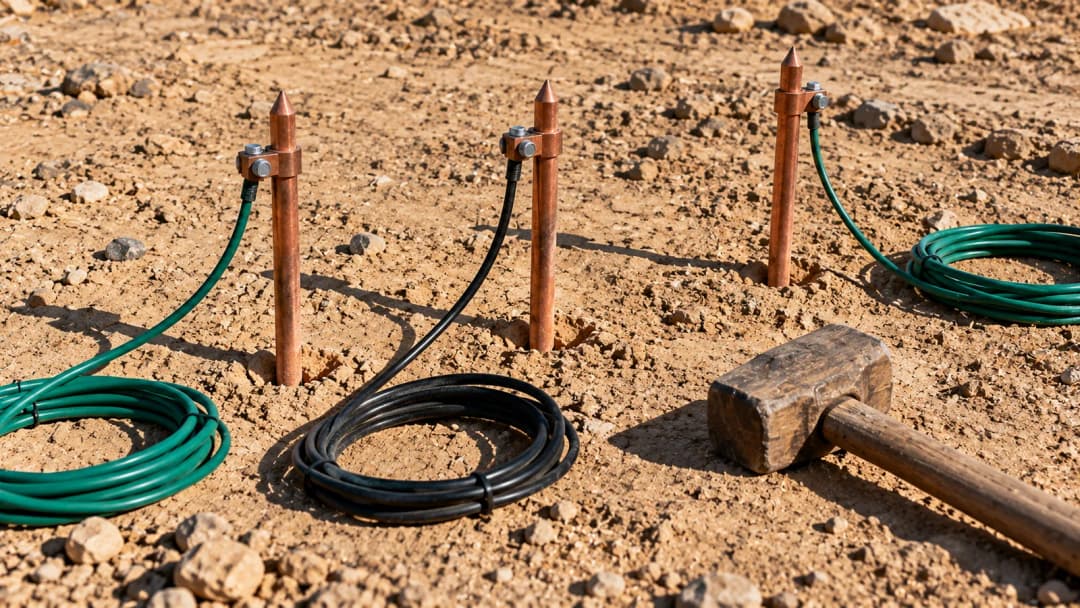
DEWA requires the main earth electrode resistance not to exceed 1 ohm for each incoming supply or main distribution board, and the resistance from any point on the earth continuity conductor back to the main earth electrode not to exceed 0.5 ohm. Earth continuity itself is held to 0.1 ohm. Those are tight figures by international standards, and meeting them in Dubai's soil conditions takes more than driving one rod and hoping.
This guide covers the limits, why UAE ground is difficult, the three ways to measure, and what to do when a reading will not come down.
The limits
| Measurement | DEWA limit |
|---|---|
| Main earth electrode resistance, per incoming supply or MDB | ≤ 1 Ω |
| Any point on the earth continuity conductor to the main earth electrode | ≤ 0.5 Ω |
| Earth continuity | 0.1 Ω |
All three go on the Inspection & Testing Certificate. The 1 ohm electrode figure is the one that causes trouble on site; the continuity figures are usually a matter of workmanship at the terminations.
Why UAE ground makes this hard
Soil resistivity is the variable that decides electrode performance, and most of the UAE is working against you. Dry sand is a poor conductor — resistivity rises steeply as moisture content falls, and in summer the top few metres dry out almost completely. Coastal sites get salt in the groundwater, which helps conductivity but attacks copper and steel, so a rod that measured well at commissioning can degrade within a few years.
Two practical consequences. First, a reading taken in February is not the reading you will get in August; measure in the dry season if you want a figure you can defend. Second, depth beats quantity. Driving a single rod deeper into damp strata usually does more than adding a second rod near the surface, and rods spaced closer than their driven depth interfere with each other and give a falsely optimistic result.
Three ways to measure
Fall of potential, three or four terminal
The reference method, and the one to use for a commissioning figure you will be held to. The electrode under test is disconnected, a current spike is driven well away from it, and a potential spike is moved between the two. Readings are taken at 20, 40, 60, 80 and 100 per cent of the distance to the current spike; a flat section in the middle of the curve is the true electrode resistance. If there is no flat section, the current spike is too close and the whole set is invalid.
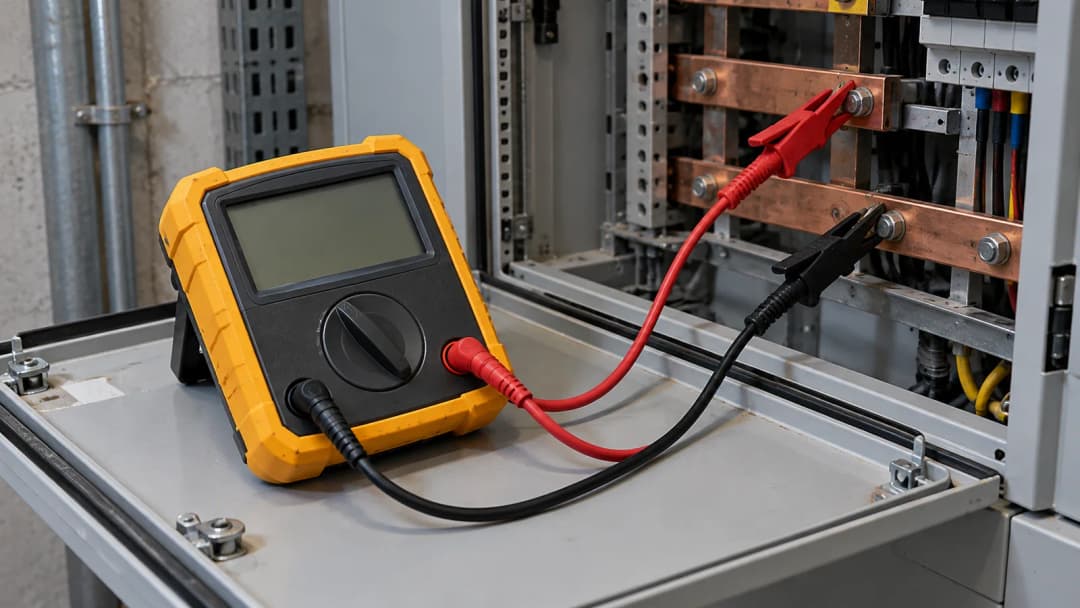
Instruments: Fluke 1623-2, Fluke 1625-2 GEO, Megger DET3TD, Megger DET4 series. Four-terminal units remove lead resistance from the result, which matters once you are chasing a 1 ohm limit.
Clamp-on, no spikes
A clamp induces a voltage into the earth loop and measures the resulting current. It is fast, needs no spikes and no disconnection, and is the only practical option on a live installation or inside a building. It also only works on a genuinely multi-earthed system with a parallel return path — on a single isolated rod it measures nothing useful.
Use it for routine checks and trending, not for a commissioning certificate. Instruments: Fluke 1630-2 FC, Megger DET14C, Megger DET24C.
Stakeless and two-pole loop
Loop impedance testers report the earth fault loop path, which includes the supply transformer and the whole distributor network — not your electrode on its own. Useful for verifying that protection will operate, misleading if quoted as an electrode resistance. Keep the two figures separate on your paperwork.
When the reading will not come down
- Go deeper before going wider. Extension rods into damp strata are usually cheaper and more durable than a wider array.
- Respect spacing. Multiple rods must be separated by at least their driven depth, or they share the same soil volume and the parallel benefit largely disappears.
- Consider a ring or mesh where rods cannot go deep — a horizontal conductor at depth around the footprint behaves well in sand.
- Bentonite or a conductive backfill stabilises the soil immediately around the electrode and holds moisture through summer. It is a legitimate engineered fix, not a bodge.
- Check the connections before blaming the soil. A corroded clamp or an unbrushed exothermic joint can account for most of a failing reading, and it is the cheapest thing to rule out.
Browse earth ground and installation testers, or the earth ground testers specifically.
Common questions
Can I certify an installation with a clamp-on earth tester?
Not on its own. A clamp measures the loop, not the electrode, and needs a parallel return path to read at all. Use fall of potential for the certificate and the clamp for routine monitoring between inspections.
How often should earth resistance be retested?
Annually as a baseline, and always in the dry season so readings are comparable year to year. Coastal and industrial sites justify more frequent checks because corrosion is faster.
Why does my reading change between morning and afternoon?
Surface moisture. Soil resistivity swings with water content, and in Dubai that changes measurably over a day in exposed ground. Record the conditions with the reading.
What covers both earth testing and installation certification?
A multifunction installation tester such as the Fluke 1664 FC handles loop, RCD, continuity and insulation in one instrument, with a dedicated earth tester alongside it for the electrode figure.
Sourcing the instrument
We hold earth testers, clamps and multifunction installation testers from Fluke, Megger and Kyoritsu in Deira. Collect from our counter on Naif Road or take delivery across the UAE in one to two working days. We supply and resell rather than hold an authorised distributorship, and we quote the same working day — send a model number and we will confirm price and stock.
Limits quoted here come from DEWA's published regulations for electrical installations. Work to the current revision for your project.